The vehicle throttle is commanded by the proportional opening of the air intake valve.
The original air intake valve was operated via the throttle pedal directly,
meaning that a steel cable connected the pedal to the valve.
Pressing the pedal would force open the valve allowing for a larger amount of
air to enter the engine; the intake valve was fitted with
a potentiometer sensor that allowed the monitoring of it's positions.
The valve position sensor is crucial to the engine management. This sensor
together with a air mass flow sensor, located in the air intake filter, define
the amount of fuel that the engine needs to inject. The command of the vehicle
throttle is performed by operating only the air intake valve and consecutively the signal associated with the valve
position.
In order to control the vehicle throttle automatically, the air intake valve had to be automatically actuated. To this end, the original valve was substituted by a motor driven valve from a different vehicle. This new valve, as the original one, also possesses a position potentiometer.
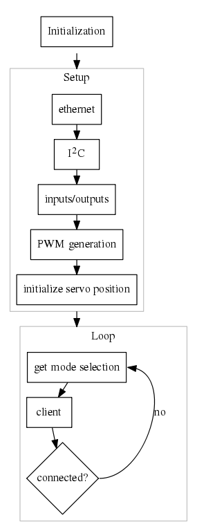
This new motor driven valve created the additional need for a motor position controller. Given that the new system should be able to be actuated by a human driver as well as a computer program, a control board was also needed. This board is responsible for reading the pedal command signal (human control), receiving an external command (automatic control) and also receiving a operation mode selection signal. It should be able to interface with the motor position controller relaying to it the correct command signal.
The main electronic components consists of an Arduino Ethernet board coupled with the motor controller from an servo motor (Hitec HS-815BB+). Between the two board exists another electronic circuit responsible for tension levels conversions and power distribution.
The following image provides a detailed schematic overview of all the components of the system.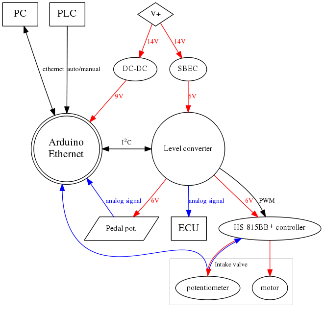
Power enters the system by a connection with the car main battery using a control relay. The input voltage is not constant, it depends on the state of the battery. If the car engine is running this voltage will remain stationary at 14V.
The 14V are converted into two different level; 9V for the Arduino and 6V for the motor controller.
In theory and according to the documentation the Arduino is able to receive 14V at input. In practice it works but the Arduino board will
overheat and the Ethernet communication will stop working. Steeping the input voltage down to 9V will solve the overheating without
any disadvantage (the Arduino will regulate it's input voltage to 5V to work with the micro-controller).
The conversion to 6V will be used to power the servo motor controller. The 6V are achieved using a Switched Battery Eliminator Circuit (SBEC)
typically used in Radio Controlled (RC) models. This circuit is in fact just a switched DC-DC converter optimized either at 5V or 6V being
able to supply 4A constant or 5A peak.
The level converter board receives the 6V from the SBEC and powers the motor controller and the pedal potentiometer.
The motor controller is responsible for the close loop control of the motor position, so it powers the motor has needed and the potentiometer attached to it. One important fact is that the motor controller powers the potentiometer with a variable tension this causes problems when trying to read the potentiometer value using the Arduino.
The Arduino signal inputs are: the automatic commands for the Ethernet connection with the PC; the hardware mode selection signal from the PLC and mode selection switch; the analog throttle pedal position; the analog throttle valve position and finally a bidirectional communication line with the level converter board.
The level converter board is equipped with 4 digital potentiometers capable of I2C communication, one of these potentiometers is used to create the Engine Control Unit (ECU) analog signal (the signal the engine uses to increase or decrease the fuel injection). This board also relays the PWM signal from the Arduino to the servo motor controller.