The mechanical design process:
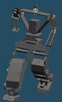
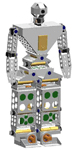
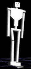
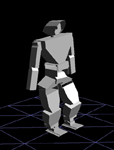
Initial design June 2001 and final design 2002
The GuRoo was designed with the proportions of a child of an approximate 6 years of age. At a height of approximately 1.2m, the robot is able to easily interface with typical human environments such as bench tops and door handles. The mechanical design of the GuRoo begun in March 2001 as an undergraduate thesis project. SolidEdge, a 3D solid modeling package was used to draft all sections of the robot before construction. The robot took physical form 1 year later.As can be seen from the pictures, the GuRoo underwent major changes throughout the design process. The majority of the structure is made from 3mm aluminium plate and angle sections. The robot contains well over 500 rivets and screws combined. The structure is heavily milled to reduce weight and improve airflow over the motors and power electronics.
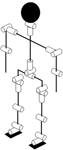
Location and Orientation of
each Degree of Freedom
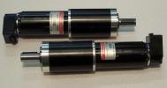
Maxon Motors
The high power necessary for the lower limbs and spine was realised with brushed DC motors. For cost reasons and ease of implementation, all lower joints use the same motor / gearhead combination. The Maxon RE32 series motor wound for a nominal 32V in combination with a ceramic 156:1, 72% efficient, planetary gearhead is used. The maximum continuous output torque available is 10Nm with a maximum speed of 5.3rad/s at 2 amps of current consumption. Maximum intermittently permissible torque available is 22.5Nm at 4A. The length of the motors dictated the width of the GuRoo's legs. With an individual mass of 0.85kg per motor / gearhead combination, the high powered motors make up 33% of the total weight of the robot.
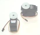
HiTec Servo Motors
Low power, low weight and ease of controllability were the factors in choosing the actuators for the upper limbs. The RC servo motors used are Hi-Tech HS705-MG, capable of 1.4Nm output torque at speeds of 5.2 rad/s at 5V. Intrinsic metal gearboxes allow a relatively large output torque from a small package. Each servo weighs 0.125kg. Each motor has an internal close loop control system, but does not provide feedback to the main GuRoo controller. Digital servo-motors, providing additional torque and accuracy, are being implemented in the head and neck.
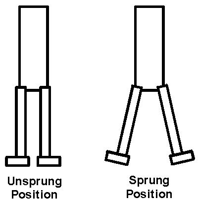
If the robot is un-powered and lifted off the ground, the legs will naturally swing together, as the centre of mass of the leg is outside the line of the hip joint. Additional torsion springs with a spring constant of 1Nm/degree are located in parallel with the hip roll actuators to prevent this from occurring. The springs are set such that when un-powered, the legs of the robot hang straight down. The additional torque from the spring also alleviates the stress on the hip roll motor during the single support phase of a typical walking gait.
As might be expected, GuRoo can only approximate many human movements. One of the most obvious is the crudely copied flexible spine. A human spine has 24 vertebrae distributed along the entire length that enables flexible motion, as opposed to the GuRoo, who has only three orthogonal actuators. Ball joints are also present in human hips and shoulders and allow high mobility actuated from a small volume. Due to the nature of the actuators used, ball joints were difficult to implement. Instead, multiple degrees of freedom have been achieved with small sequential links. All degrees of freedom are orthogonal when the robot is in a standing position.
The GuRoo is powered by two 42V 1.5Ah NiCad battery packs and two 7.2V 1400mAh NiCad packs on each board. The 42V packs are used in parallel as the supply for the DC motors, while the two 7.2V packs are used to power the servos and the logic respectively. The use of different power sources for different power rails prevent noise generated by the high power switching of the motors from affecting the supply for the logic circuitry. Local regulation on each board converts the 7.2V rail down to the 5V necessary for the logic circuitry. The power board located in the rear of the torso is responsible for distributing power from the 42V packs to each motor board. Load sharing is achieved through the use of high power diodes that prevent one battery pack discharging into the other. A large 'kill switch' cuts the batteries from all boards in the event of an emergency.
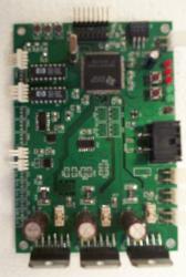
High Power Motor Controller
The eight RC servo motors are positioned by eight individual pulse length control signals from a single controller board. Each signal has a carrier frequency of 50 Hz, and is buffered through a CMOS 4024 buffer to supply 7 volts to the RC servo inputs. Each RC servo contains internal electronics and a potentiometer for local control. This internal feedback prevents the DSP from distributing the actual velocities of the upper body motors back to the central controller, or performing any form of alternate control. As such the motors are controlled by a position profile, updated at the carrier frequency of 50 Hz.

Compaq iPAQ PDA
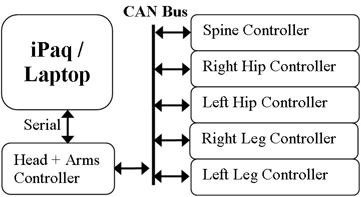
Electrical Architecture
Early simulator and the current implementation
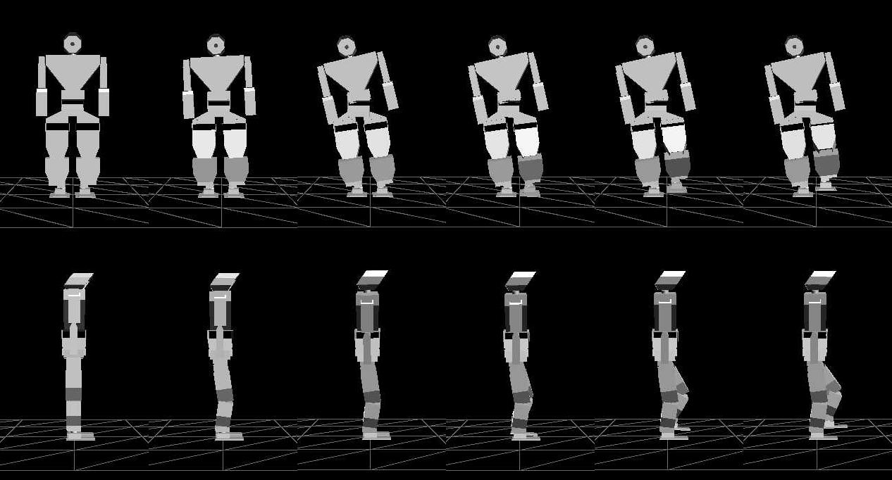
An example of a simulated 'Standing on One Leg' motion
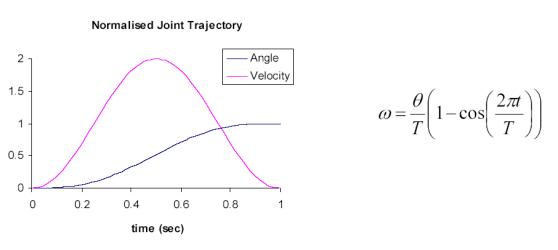
where omega is the desired joint velocity, theta is the desired change in joint angle and T is the period of the movement. This profile ensures the joint experiences zero acceleration at the start and end of each movement which minimises the jerk and vibration. Zero velocity at the start and end of each trajectory allow for smooth transitions between trajectories. The velocity for all 23 degrees of freedom is calculated at 50Hz.
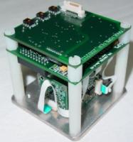
Electronic Inertial Measurement Unit
The GuRoo has several sensors capable of providing the feedback necessary to achieve stable walking. A 500 count per revolution encoder located on each high powered motor provides measured joint position to an accuracy of 0.001 degrees.
A custom built inertial measurement unit by CSIRO can provide spatial orientation information from it's 3 axis gyroscopes, accelerometers and magnetometers. Currently the eIMU is connected via the CAN bus, and provides the central controller pitch and roll axis measurements of the torso with respect to the ground.
Work is currently underway to implement pressure sensors in the soles of the feet.
The GuRoo vision system is still in it's infancy and has yet to be fully deployed on the research platform. Two OmniVision CMOS camera's provide 240x480 pixel images to a Hitachi SH4 processor at a rate of 20 frames per second. This dedicated vision board performs color segmentation and basic shape localisation and recognition. This information is then sent to the central controller.
This Page Last Updated:
15th Jan 2004
Copyright Damien Kee 2004
damien@itee.uq.edu.au