Design and Characterization of a Strapdown Inertial
Navigation System based on Low Cost Sensors
Students project at the
Electronics Laboratory of the Swiss Federal Institute of Technology, Zurich,
Switzerland
Students: Peter Luethi, Thomas Moser
Assistant: Markus
Uster
Design, Testing & Measurements: April 2000 - July 2000
Table of Contents
Preface
Introduction
Physical
& mathematical background
Aim of this
project
System
concept
System
architecture
Measurements
Enhancements
to increase accuracy
Conclusions
& Outlook
References
Available
resources
Acknowledgements
The design of an inertial navigation system is a very complex issue and
requires profound skills in analog circuit design, signal processing and
algorithm programming. I have not the time to answer all possible questions
about this subject and to provide support for any occuring problems.
Please
refer first to the literature
references stated at the end of this page.
Inertial navigation is based on techniques, which have been invented and
developed after the Second World War. The first systems were built of mechanical
gyros, which required very complicated technical and power consuming
constructions being prone to failure. Later on 'solid state' solutions have been
realized by using only discrete integrated electro-mechanical or electro-optical
sensors. These 'solid state' systems had no moving parts (therefore Strapdown
Inertial Navigation System), but consisted of expensive laser-gyros and
integrated sensor devices in MEMS technology (Micro
Electro-Mechanical System).
Inertial navigation
systems (INS) are used in civil and military aviation, cruise missiles,
submarines and space technology. According to these areas of operation, the
entire system and all components have to be very precise and reliable. As a
consequence, the costs for such a system are still very high
(> 100'000 US$) and the size is not yet as small that it can be
used for mobile roboting, wearable computing, automotive or consumer
electronics.
But applications designed for these industry branches ask for a
very small and inexpensive implementation of such a strapdown INS. Industrial
demand for low-cost sensors (car airbag systems) and recent progress in MEMS
integration technology led to sophisticated sensor products, which are now both
small (single chip solution) and inexpensive (~100 US$).
 |
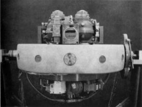 |
| Navaho test missile X-10 after completing first unmanned aircraft flight under control of inertial navigation guidance USA, September 1956 | |
A body's actual spatial behavior / movement can be described with six parameters: three translatory (x-, y-, z-acceleration) and three rotatory components (x-, y-, z-angular velocity). To be able to define the movement of the body, three acceleration sensors and three gyros have to be put together on a platform in such a way, that they form an orthogonal system. The distance laid back and the angle the body has actually rotated can be obtained by integration of the individual translatory and rotatory components. Performing these calculations accurate and periodically enables the ideal system to trace its movement and to indicate its current position and heading.
 |
.gif) .gif) |
| The six parameters of freedom A body's actual spatial behavior / movement can be described with three translatory and three rotary components. | |
The main limitation of the system performance is given with the finite precision of the sensors. A continuous small error in acceleration will be integrated once and results in a big error in actual speed, integrated a second time in a huge error in distance. Therefore very precise sensors and error correction mechanisms (feedback algorithms) are necessary to get an accurate inertial navigation platform. As an example, a 'cheap' feedback algorithm is the g-vector method. It does not require additional hardware, but simply assumes that the average direction of the z-acceleration vector points exactly rectangular down towards the earth surface and its average value is -9.81 m/sec². Another feedback method is the introduction of GPS position data fed to the INS, but this concept requires careful considerations about the update mechanism for not disturbing the entire system, especially in case you want to control devices and not simply measure their movements!
Another difficulty (for not introducing another problem) which needs careful
evaluation is the choose of the right system coordinates to be used. There exist
different solutions - some of them with added redundancy to allow for improved
precision.
We have chosen the representation based on 'Euler'-angles. It is
defined by 3 axis: roll/bank (alpha), pitch (beta) and direction (gamma). The
translation to the components referring to the initial system proceeds as
follows: (x"', y"', z"') =(alpha)=> (x", y", z") =(beta)=> (x', y', z')
=(gamma)=> (x, y, z) .
|
Representation of the body's actual spatial situation (x"', y"', z"') referring to the initial system (x, y, z) by using 'Euler'-angles. |
|
Calculation of the actual acceleration (dx, dy, dz) referring to the initial system (x, y, z) and using the mathematic transformation based on 'Euler'-angles. |
|
Calculation of the actual angular velocity (dalpha, dbeta, dgamma) referring to the initial system (x, y, z) and using the mathematic transformation based on 'Euler'-angles. |
For further information please refer to the literature
references at the end of this page.
Our task was to realize a portable strapdown inertial navigation system based
on low cost acceleration sensors and gyroscopes. Low cost in the context of this
project means sensor costs of up to US$ 500. First we had to find a
feasible implementation concept (as simple, fast and accurate as possible),
afterwards we had to design and build up the complete system consisting of
hardware and software.
At the end, we had to be able to state what precision
has been achieved and, if applicable, where possible bottle-necks are located.
Finally, there should also be conclusions and an outlook for further
improvements.
We decided to realize our system based on the following concept allowing for quick software based changes on algorithms, convenient visualization and user interface, 'unlimited' processing resources and storage capacity:
Relying on this approach, we were able to focus entirely on the realization
of the low cost INS and its specific problems and did not have to cope with
other problems, such as limited hardware (program memory) and processing (MIPS,
FLOPS) resources, finite precision (IEEE 754 floating point standard), all
possible hardware related problems (device programming), tools (IDE: simulation,
debugging), ...

Gyro ENC03 as removable building block in a short 14 pin wide dual inline package (x- & y-axis) |

Gyro ENV05 vertically
mounted |

Acceleration sensor ADXL210 as removable building block in a short 14 pin wide dual inline package |
All sensor outputs are first led to second order Butterworth low pass filter stages to prevent aliasing and to reduce noise. These filters have a cutoff frequency of 50 Hz (except the filter for the precise gyro, which has only an output response frequency of 15 Hz) and are followed by an amplifier to perform optimum signal range adaptation at the analog inputs of the DAQCard1200. The A/D converter has different voltage input ranges, we decided to work in the 0 - 5V input range of the A/D converters.
The software features all necessary structures to fetch acquired data and to
calculate and display actual accelerations, angular and translatorial speeds,
and the current position. Since my colleague and I are both familiar with
airplanes and related instrumentation, we implemented an artificial horizont and
a directional indicator (virtual compass). This 'instrumentation' provided very
valuable help during debugging of the entire INS, and last but not least, served
later on for convenient (and impressive!) visualization of our
achievements.
|
Data flow chart of our strapdown inertial navigation system
(INS) |
Data flow chart as PDF file: SystemFlow.pdf
(23 kB)
Software flow chart as PDF file: SW-Flow.pdf (2 kB)
|
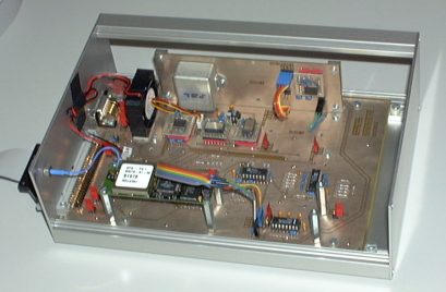
The final sensor board |
|
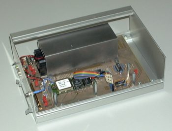
The sensor board with mounted airflow channel to get the ability for measuring a defined temperature uniform distributed over all sensors. But it is very important to keep the entire system at a place with minor temperature variations for not giving rise to dynamic temperature induced errors. |
|
The final setup: Strapdown Inertial Navigation
System |
| Static Spatial Representation Measurements | |||
| Sampling Rate | 150 Hz | 300 Hz | 500 Hz |
| Horizont after 30 sec | 2.5 deg | 2.0 deg | 2.0 deg |
| Direction after 30 sec | 0.7 deg | 0.5 deg | 0.5 deg |
| Horizont after 60 sec | 5.0 deg | 5.0 deg | 5.0 deg |
| Direction after 60 sec | 1.5 deg | 1.1 deg | 1.1 deg |
| This measurement shows the drift of our INS, not being moved in any direction, without any feedback or update mechanisms active. | |||
| Dynamic Spatial Representation Measurements | |||
| No adequate test equipment to make exact quantiative statements. It is important that the maximum angular velocity of the gyros is never exceeded (slowest device ENV05: +/- 80 deg/sec). Up to 30 degree swing, the resulting error is quite the same for all sampling frequencies. For larger swings, the magnitudes of error are dependent on the sampling frequency. |
| Static Position Measurements | |||
| Sampling Rate | 150 Hz | 300 Hz | 500 Hz |
| Deviation after 30 sec | 8 m | 8 m | 8 m |
| Deviation after 60 sec | 40 m | 40 m | 40 m |
| Static position measurement means that the INS was not moved in any direction. We just measured the accumulating position error. The g-vector feedback mechanism was active. There has not been used any GPS data during all these measurements in order to get information about the achieved precision of our INS platform. It is obvious that in conjunction with additional GPS data, the characteristics of the entire system can be improved. | |||
| Dynamic Position Measurements | |||
| Useless at the moment. Does only make sense in conjunction with additional GPS data, but then we will measure the GPS accuracy and no longer the qualities of our INS platform. |
There exist several approaches to increase overall system performance. From our perspective, there are two important issues to be taken into consideration. First, to start up a precision measuring instrument, a thorough initial calibration is stringent. Most often, the initial calibration is carried out with a object not being moved. This is also known as static calibration. Second, to keep up the precision achieved from the calibration procedure at start up, it is very important that we sustain dynamic calibration during the entire time of operation. This is necessary because our system does not have infinite precision and the output values of our components are prone to drift away.
The strapdown inertial navigation system as described before does not feature enough resources for standalone and accurate initial static calibration. The inherent problem is that we want to calibrate six independent components - three rotatory and three translatory. To carry out precise calibration of all these components, the following two preconditions have to be met:
These two preconditions provide data necessary to correct any deviations in sensor alignment and to calibrate the system according to the current sensor output values. Our INS platform relies on precise horizontal alignment, exact heading towards north, and a vertical g-vector of -9.81 m/sec² during initial calibration.
Note, that the above horizontal static calibration activity is only targeting the zero values of the sensors. Any life-time induced alterations in sensor sensitivity can neither be detected nor corrected by this calibration procedure. On contrary, to be able to detect changes in acceleration sensitivity, it is required to place the INS box first in normal position, then x- and y-side up and down, and finally bottom-up. But this procedure only targets the acceleration sensors, the gyroscopes still remain for calibration.
To achieve a significant increase in accuracy even with insufficient sensor precision, a very powerful method is the introduction of adequate feedback mechanisms. We provide hereafter an enumeration of feasible feedback mechanisms applicable for dynamic calibration of inertial navigation systems. It can not be viewed as exhaustive.
| Feedback Mechanism | Description | Remarks |
| g-vector feedback | Concurrent calibration through calculation of magnitude and resulting direction of (average) acceleration vector (g-vector) | Assumption: The system is not used in a constantly accelerated environment, e.g. constant rotation. The system may need pauses to re-achieve its precision. |
| Electronic compass | Concurrent calibration of heading (direction updated/provided by z-axis gyroscope) | Compass may be disturbed by electromagnetic fields or metals, maybe only operating in horizontal (initial) position of entire system |
| Static GPS data (object not moving) | Concurrent calibration through calculation of actual position and speed (zero speed) | No GPS coverage in tunnels and cities with tall buildings |
| Dynamic GPS data (object moving) | Concurrent calibration through calculation of actual position, speed and heading (resulting direction of movement) | No GPS coverage in tunnels and cities with tall buildings |
| Component | Applicable Mechanisms for Dynamic Calibration |
| Acceleration, x-axis | g-vector feedback, static & dynamic GPS data |
| Acceleration, y-axis | g-vector feedback, static & dynamic GPS data |
| Acceleration, z-axis | g-vector feedback, static & dynamic GPS data |
| Angular velocity, x-axis | g-vector feedback, dynamic GPS data (if object is rotating or following a constantly bended path) |
| Angular velocity, y-axis | g-vector feedback, dynamic GPS data (if object is rotating or following a constantly bended path) |
| Angular velocity, z-axis | g-vector feedback, dynamic GPS data (if object is rotating or following a constantly bended path), electronic compass (only in horizontal position of object) |
An inertial navigation platform built of low cost sensors is basically
possible. Although the achieved precision is sufficient for measuring the actual
spatial representation (angles & acceleration), further improvements have to
be realized in algorithms and hardware to get also sufficient accuracy for
position measurement. At the moment, getting accurate data of the current
position is impossible due to the limited precision of the sensors. Our system
needs at least an increase in sensor precision of a factor of 10. We think that
it is just a matter of time until this requirement is met by the advance in both
sensor device engineering and manufacturing technology.
Corrections of
systematic errors such as temperature drift, non-linearities, and sensitivity
deviations can lead to significant improvements in overall system performance.
With the aid of adequate feedback mechanisms (g-vector, GPS position) and signal
processing algorithms (average building, kalman filtering) further improvements
in precision can be achieved.
| C. F. Donnell et al., Inertial Navigation, Analysis and Design, McGraw-Hill, 1964 |
| D. H. Titterton and J. L. Weston, Strapdown Inertial Navigation Technology, Peter Peregrinus Ltd., 1997 |
| Anthony Lawrence, Modern Inertial Technology, Springer Verlag, 1993 |
| E. Nebot and H. Durrant-Whyte, Inertial Calibration and Alignment of an Inertial Navigation, in M2VIP'97, 1997, IEEE Press |
| E. Nebot, S. Sukkarieh, H. Durrant-Whyte, Inertial Navigation aided with GPS Information, in M2VIP'97, 1997, IEEE Press |
| German PDF documentation: | INS_doc.zip (4.04 MB) | |
| Visual Basic 5.0 source code: | Cockpit.zip (38 kB) |
Special thanks to:
| My team member, Thomas Moser, who gave best efforts to cope with the software based problems. | |
| Matthias Nykos, Simon Maurer, Thomas Zwicker, Lukas Karrer, Pele and Bruno Wuethrich for joining our coffee breaks, and providing coffee powder, chocolate rabbits, and other ingredients. | |
| Electronics Laboratory of the Swiss Federal Institute of Technology, Zurich, Switzerland for the hardware support. |
Last updated: 05.01.2003