 |
|
|
|
|
|
|
|
|
| |||||||||
|
Merlin Systems Corp. Ltd |
 |
|
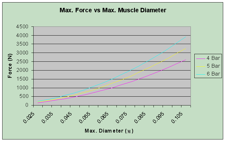
The graph above depicts the Max. Force available for a muscle at varying pressure for a given maximum muscle diameter. The Max. Force on the Y-axis is in Newtons. The Max. Diameter on the X-axis is in meters(M). The Max. Diameter is measured when the muscle is fully contracted. The profiles are shown for muscles at three different pressures 4, 5 and 6 Bar. The graph is based upon a mathematical model that has been tested against a variety of actual muscles under different conditions. It should be used as a guide only. The Max. Force of a muscle is available when the muscle is fully extended, as the muscle contracts the available force drops as a function of length. |
 |
||||||||||||||||||||||||||||
|
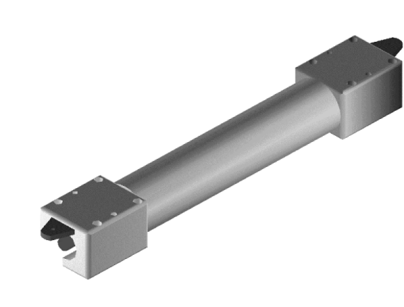
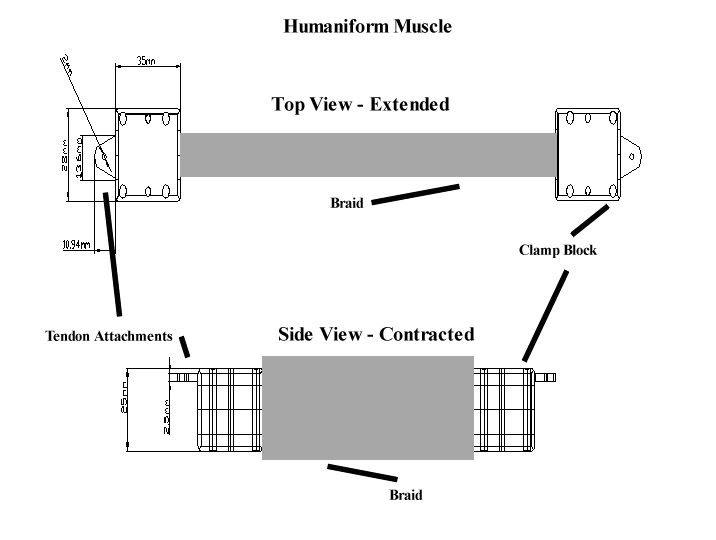
The diagram above depicts the major dimensions of the Humaniform Muscle. The clamp blocks have 4 M3 mounting holes which are left empty for customer use. Each clamp block also has a protruding lug for the attachment of tendons. Tendons allow the muscle to apply force at a distance. The material used for “tendon” depends on the force of the muscle, we have used catgut, nylon cord and metal cord (stranded steel wire). |
||||||||||||||||||||||||||||
|
||||||||||||||||||||||||||||
|
||||||||||||||||||||||||||||
 |
||||||||||||||||||||||||||||
|
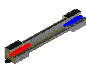
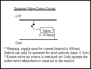
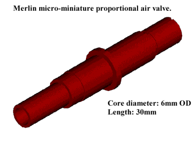
Each clamp block is supplied with integral electrical connectors to supply power to drive the internal air valves (shown above). We supply the matching connector ends with each muscle for customer use. The internal air valves are operated by passing current through a Shape Memory Alloy (SMA) wire. The amount of airflow is proportional to the electrical power supplied through the SMA wire. Each valve behaves like a resistor (1.5 -> 1.8Ohms), the power dissipated though the SMA wire causes heating. The higher the energy input the faster the valve will operate. The compressed air flowing past the wire causes cooling, the higher the air-pressure the faster the cooling. Care must be taken to ensure the SMA wire is not overdriven. A short pulse(upto 0.5s) of 500mA (5v) can be used when connected to an airline at 3 Bar or higher. A simple drive circuit is shown below. This circuit must be used in conjunction with a current limited supply. Musce failure due to overdriven SMA wires is not covered under warranty. |
||||||||||||||||||||||||||||
|
|
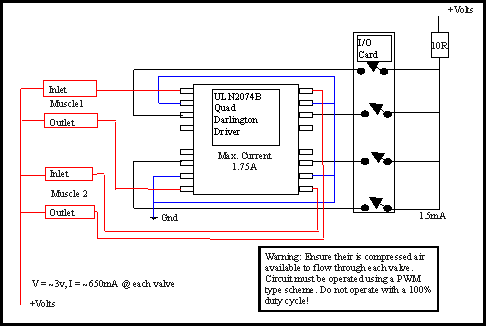
It is often desireable to drive the valves under computer control. Most small micro controllers can only suply about 25mA of current. To increase this we can use a transistor with a higher supply (the diagram below shows a quad transistor package). To use the valve proportionally we can use a PWM (pulse width modulation) drive. We can vary the duty cycle to alter the air flow through the muscle. A quad darlington array can be used (such as the ULN2074B) to drive upto 4 valves (2 muscles). Below is a sample circuit. |
 |
|
|
Each clamp block terminates in a 4mm push fit fixing (accepts 4mm air hose directly). Air passes through the muscle in one direction only (inlet valve has a pneumatic fixing). To prevent overdriving of the inlet valve it is advisable to provide a safety interlock to prevent the muscle operating during low pressure conditions. There are a number of ways of supplying compressed air. The most common is to use an air compressor. Air compressors are either oil free (noisy but clean) or oil filled (requires an oil filter but very quiet - like a fridge compressor). You can get these ranging from very compact (e.g. tyre compressor) to very large (industrial type). Many applications have readily available sources of compressed air but if you require a portable air supply then there are a number of options. Compressed air cylinders are perhaps the most readily available. These are typically used by divers and other uses such as paint ball guns. Compressed air can also be generated by chemical means although we have not tried these yet (let us know if you have!). We have attached a tyre compressor with onboard batteries to a an air cylinder (as a reservoir). We then replaced the switch in the tyre compressor with an automatic pressure switch to give a fully independent air supply!
|
| [Sensors] [HumaniformMuscle] [Downloads] [Robotics] [About] [Company] [Service] |
|
ITTC Tamar Science Park, 1 Davy Road, Derriford. Plymouth. England. PL6 8BX |
||||
|
Patents Pending: 0013036.9, 0021359.5. Webmaster: sales@merlinsystemscorp.co.uk |
||||
|
Humaniform, Digilog, Stretch Sensor, LEX &
MIABOT are Trademarks of Merlin Systems Corp. Ltd |
||||
