| Pneumatic Robot (SoftArm) | |

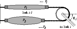
When air pressure in a rubbertuator is increased, the diameter of the tube increases thereby causing the length of the tube to decrease and the joint to rotate. Stiffness of the joint is determined by the total pressure in both the agonist and antagonist tubes such that the compliance of individual joints may be varied. The resulting flexibility, obtained using this variable compliance, combined with a high force-to-weight ratio, is well suited to a number of applications, such as human-robot interactions. Use of rubbertuators, however, leads to both nonlinear and hysteretic behavior, for example the pressure-position relationship changes over time. In consequence, accurate positioning of the SoftArm presents a challenging problem. A more detailed description of the mechanical characteristics is given in: Neural Network Control of a Pneumatic Robot Arm (Ted Hesselroth, Kakali Sarkar, P. Patrick van der Smagt, and Klaus Schulten)

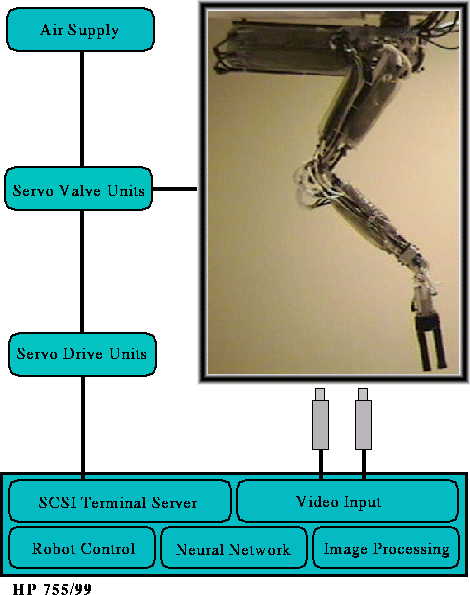
Diagram of the robot system, showing SoftArm, air supply, control electronics and workstation. The host computer includes a software layer (robot control, neural network and image processing programs) and the hardware components (serial interface and video input).
The complete robot system, which is depicted in the figure above, consists of the SoftArm, air supply, control electronics (servo drive units) and an Hewlett Packard HP755/99 workstation which includes a serial interface, connected to the robot's servo drive units, and a video input card (Parallax Power Video 700Plus). The servo drive units provide the internal control circuitry of the robot, operate the servo valve units and send joint angle data, available from optical encoders mounted on each joint, to the computer.
Visual feedback is provided by color video cameras. For maximum flexibility, vision processing is implemented in software rather than in hardware. The use of a frame grabber to import the video signals in a JPEG encoded format minimizes the amount of data to be transferred between the video board and workstation memory. The location of the gripper is extracted from the video frames through a simple color separation, yielding one color component. This is then thresholded and the center of mass of the remaining image calculated. Coding the gripper in a certain color, e.g. red, allows us to weaken the workspace scenery restrictions in terms of background and lighting conditions while, at the same time, keeping the visual preprocessing as simple and efficient as possible.
Materials on this site are copyrighted. Modified 10/30/96
webserver@ks.uiuc.edu