 |
|
|
|
|
|
|
|
|
| |||||||||
|
Merlin Systems Corp. Ltd |
||||||||||||||||||||||||||||||
|
|
||||||||||||||||||||||||||||||
|
||||||||||||||||||||||||||||||
|
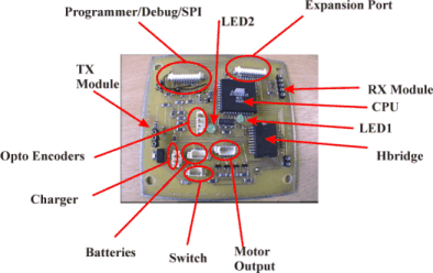
MIABOT Control Board The MIABOT control board is designed using the latest surface mount technology to create a compact feature packed general purpose control board.
|
||||||||||||||||||||||||||||||
 |
||||||||||||||||||||||||||||||
|
||||||||||||||||||||||||||||||
|
Software Each robot is supplied with the GNU ĎCí compiler, download utility (dos,windows 95,98,NT & Linux), editor and other development tools. For most users this is everything they need to get started. Please visit this page for an overview of the build tools. The MIABOT RDK is supplied with each robot providing basic (but extensible) motion control software. Corresponding sample code is provided to run on the PC to control the robot (QBASIC and Visual C++). A BASIC development environment for the robots can be supplied at additional cost. |
||||||||||||||||||||||||||||||
|
PC Transmitter Each robot can be driven via the debug cable or wireless communications. To communicate with the robot use the PC Transmitter unit which plugs into the 9-Way RS232 port. Specify the transmitter frequency (418Mhz or 433Mhz) to match the RX module on the robot. A single PC transmitter can be used to communicate with multiple robots by sending out communications packets each with a unique id. The software on each robot can be then tuned to only respond to commands with the correct id. |
||||||||||||||||||||||||||||||
|
Programming robots Information about programming robots can be found here. |
|
Further Documentation
|
| [Sensors] [HumaniformMuscle] [Downloads] [Robotics] [About] [Company] [Service] |
|
ITTC Tamar Science Park, 1 Davy Road, Derriford. Plymouth. England. PL6 8BX |
||||
|
Patents Pending: 0013036.9, 0021359.5. Webmaster: sales@merlinsystemscorp.co.uk |
||||
|
Humaniform, Digilog, Stretch Sensor, LEX &
MIABOT are Trademarks of Merlin Systems Corp. Ltd |
||||