There are two approaches to modelling walking machines:
In dynamic stability inertia effects predominate. In fact locomotion can be thought of as a series of ballistic trajectories with the legs being used to absorb the dynamic forces on impact before delivering an impulse for the next step. You need high speed sensors and actuators, hefty power supplies and considerably computing power for this class of robot, well beyond the resources of most if not all amateur robot builders. Indeed most experimental dynamically balanced robots are tethered with an umbilical supplying power and computer resources.
In the quasi static approach, inertia effects are ignored and the robot must be statically stable at all times. That is the gravity vector through the centre of gravity(C.o.G) of the robot must pass through the support polygon described by the leg-ground contact points. Since at any time three legs must be on the ground, for any locomotion, the robot must have at least four legs. In practise when each leg can move independently, it is difficult to guarantee that the C.o.G always lies within the support polygon with only four legs and most quasi static robots have six legs with a bilateral symmetry, the so called insect configuration. This is fine going in straight lines but turning is tedious (rather like turning in a rowing boat), and some people use six or eight legs disposed with a polar symmetry, so that they can walk in any direction. These are more complicated in that each leg needs at least three degrees of freedom.
All my robots are designed as quasi static models. Note that in the real world, there are significant dynamic effects, particularly when the robot is walking at full speed and a factor of safety should be used with the values obtained from a purely static analysis. The C. of G. and centroid will not coincide, so that the gravity vector will not pass through the centroid of the support polygon even when the robot is static on level ground and the load in each of the support legs will not be equal. In Rodney 3, the battery pack is mounted on clips and since there is no internal stiffening frame, it can be slid along the bottom tubes to trim the robot in the pitch direction.
A robot's gait is the sequence of leg movements it uses for each step cycle, where a cycle is complete when the leg configuration is the same as it was when the cycle was initiated. With six legs there are many gaits which satisfy the stability conditions for quasi static robots but two popular ones are:-
In this gait, the legs are divided into two sets of three legs. Each set comprises of the front and rear legs on one side along with the middle leg on the opposite side. A forward step half cycle starts with one set of the legs lifting and moving to a forward position. At the same time the motors of the legs in contact with the ground swing backwards the same amount moving the body of the robot forward. The lifted legs are then lowered completing the half cycle. The lifting and support sets are interchanged and the second half of the cycle is completed. This is the fastest stable gait. During the step, the weight of the robot is only supported on three legs and if one fails to find firm footing, the robot will fall.
A more stable but slower choice is the wave gait where only one leg is lifted at a time. Starting with a back leg, it is lifted and moved forward. All the other grounded legs are motored back by one sixth of the amount of the forward motion. The lifted leg is then lowered and the process repeated for the next leg on the same side. Once the front leg has been moved, the procedure is repeated for the other side. The attraction of this gait is that there is always at least five legs supporting the weight of the robot, but the forward speed is only one sixth of the alternating tripod gait.
Tom Thornton of M & T Systems has an ingenious design for a six legged walker HexWalker which only uses three RC servos. M & T Systems have discontinued this robot but I think that Milford Instruments still supply their clone Stamp Bug. On each side, the front and rear legs are linked so that one RC servo can be used to move the two legs forwards and backwards. The third servo is connected to the middle pair of legs so that rotation of the servo pushes one leg down while lifting the other. The fixed alternating tripod gait is a "pole vault" about the down middle leg, driven by the front and rear legs on the opposite side. HexWalker lacks the independent leg control needed for intelligent obstacle climbing.
A leg needs only two degrees of freedom (forwards & backwards, up & down) to move. To control the lateral placement of the foot an extra "knee" degree of freedom must be added. The consequences of moving from 2 d.o.f. to 3 d.o.f. legs are not trivial:-
I'll leave the three d.o.f. robots to the academics and amateurs with longer pockets!.
For my robots
Total weight of robot including batteries: 1.1kg
Maximum available torque T: 0.3Nm.
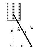
 Fig (a)
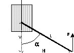
  Fig (b)
 Available Support Force F = T/H where H = L*sin(Alpha) and V = L*cos(Alpha) If L = 95mm, then Configuration A - Walking 1. High Angle If Alpha = 30°, then V = 82mm, H = 47.5mm and F = 6.3N or 643gf which would support a robot of 1.9kg in the tripod stance. 2. Limit Case For the largest Alpha angle which will support a 1.1kg robot in tripod stance F = 367gf, then H = 81.8mm, Alpha = 59° and V = 48.3mm. Configuration B 3. Standing up If V = 10mm, then Alpha = 84°, H = 94.5 and F = 3.2N or 324gf. Using all six legs, this should lift up to 1.9kg.This type of leg has three disadvantages when climbing obstacles:
 Fig
(c)
 Available Support Force F = T/H where H = Constant for Alpha1 < Alpha < Alpha2 If H = 50mm, then F = 6N or about 611gf.This would support up to 1.8kg in the tripod gait for all positions of the legs. This gives a reasonable safety margin for a 1.1kg robot. The attitude of the foot varies by about 5° throughout the 90mm vertical step range.
The strategy for stepping over small (<40mm) obstacles is to lift the leg to it's maximum height, swing the leg forward and then lower the leg vertically until the foot switch is triggered by the obstacle when the downward motion is stopped.
In my design, as the legs are swung forwards and backwards, the foot moves in a circular arc. This results in a lateral mismatch between the extreme forward and backward positions and the centre position which must be accommodated in the leg mechanism or by lateral slippage of the foot on the ground.
For a half swing angle of Alpha and a radius R

  Step_length = 2*R*sin(Alpha)

and

  Scuff = R*(1 - cos(Alpha))
Looking at a few numerical values is instructive. Here are a few values for a
radius of 50mm ( 30mm offset + 20mm of servo casing)
| Angle Alpha | Step Length | Scuff |
|---|---|---|
| 5° | 8.6 | 0.19 |
| 10° | 17.4 | 0.76 |
| 11.5° | 20.0 | 1.01 |
| 15° | 25.8 | 1.7 |
| 20° | 34.2 | 3.0 |
Even the most meticulously made linkages have some slip of a millimetre or so at the foot, so that providing that the step length is limited to about 25mm, lateral slip is not much of a problem.
I designed a stubby four bar linkage for the swing movement. My best effort gave a maximum step length of about 22mm with a maximum mismatch of about 0.8mm. This option was unattractive given the work, complexity and weight of these additional parts for no significant benefit!.
Note that during turning much larger swing angles are used and slippage does occur. The robot doesn't seem to mind!.

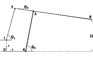
Equation for closed loop 0,1,2,3,4,0

In x direction
  F1 = r12*cos(Th1) + r23*cos(Th2) - r34*cos(Th4) - r40 = 0

In y direction
  F2 = r01 + r12*sin(Th1) + r23*sin(Th2) - r34*sin(Th4) = 0

  dF1/dTh2 = -r23*sin(Th2)

  dF1/dTh4 =  r34*sin(Th4)

  dF2/dTh2 =  r23*cos(Th2)

  dF2/dTh4 = -r34*cos(Th4)

Horizontal offset of foot at point 5

  H = r34*sin(Th4) + r35*sin(Th2)
To calculate trajectory of point 5, increment control angle Th1 and for each position solve numerically for angles Th2 and Th4 by using Newton Raphson iteration using:
Jacobian matrix J = [dFi/dThj]
Given some guessed initial configuration, the link lengths can be optimised for a desired offset H, by embedding the equation solving code inside an optimisation loop and minimising the sum of the squares of the difference H and the desired offset as Theta1 is incremented from the start to finish angles.
Sample code for Newton-Raphson iteration and various optimisation strategies can be found in references[7], [17].
This shows one of many coupler curves investigated for the trajectory of the foot of the leg and is the current favourite for the Mk 2 Improved Leg. The distance AE was fixed by the dimensions of the servo motor casing and the length CF was chosen so that two legs could be cut from one 1 foot length of alloy tubing. The other lengths were as determined by the optimising program rounded to the nearest half millimetre.
AB = 26, BC = 58, CD = 36.5, DF = 112, DE = 71 and AE = 35. The foot travels 90.5mm as the driven lower link rotates through 100°.