University of Puerto
Rico
Mayaguez Campus
Electrical
Engineering Department
Undergraduate Research INEL 4998
Nitinol Propelled Hexapod Robot
![]()
|
|
|
Utilizing the multiple properties of Nitinol wire, we constructed three Nitinol Propelled Hexapod Robots. The optimal advantage of using this material is that we did not need an electrical or mechanical motor to produce the movement in the robots. Nitinol was used as an actuator to provide the primary driving force. These robots were assembled differently in control and walking configurations. We compared the different robots in terms of speed, weight load, and efficiency. Part of the effort was to develop a mathematical model to predict movement and speed of the assembled devices. The results of this investigation will determine configuration efficiency and future applications of this type of equipment.
Problem statement
This project consists of the construction and analysis of three Nitinol Propelled Hexapod Robots. Our goal is to determine which of the models is more efficient. We will derive a mathematical model that will predict the behavior of the robot. Then a comparison between three different walking sequences will be done.
Methodology To better understand the behavior of this robot, we divided the analysis into two different parts. First we considered the physical characteristics of the Nitinol, which is the material that actually propelled the robots. Then we described the mechanical characteristics of the robot itself to understand how it walks. This should provide us with sufficient information to determine if the robot can be successful. The first step in building the robots was to cut all the tubing, since it was the most time consuming. These pieces were sanded to remove small pieces of metal that resulted from cutting. Measurements were taken to determine the amount of spare parts we had for repair in case something went wrong. Then we started bending the wires that give support to the robot. These wires, which are actually the legs, were then inserted into the body of the robot. The next step was to cut the Nitinol and to connect it to the robot by the leg and body crimps. The last step was connecting the control wires to the robot and the manual controller. The control wires were also sanded to allow proper current conduction. We followed a detailed procedure for analyzing the three robots. First we determined what kind of walking sequence the robots would have. The sequences selected depended on the degree of variation between them and on the potential they could have on an application. Since the sequences would be different for all three robots, they should give us an idea of the potential the robots could provide. The current needed for each model was also measured. After building the robots with the three different sequences, we measureed their speed. We selected a common surface on which to test the robots. We chose a porous book cover that seemed to provide us with both traction and smoothness. The electric pulses applied were equally spaced and lasted the same amount of time. Pulling force was then measured taking a small weight and letting it hang freely with a pulley. As the robot walked, the weight was raised. If we increased the weight, the estimated maximum pulling force was measured. After all the physical calculations are made, an important part of the investigation took take place. This was deriving a mathematical model that will predict the behavior of the robot.
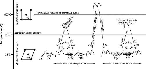
Physical Characteristics To analyze the physical characteristics of this robot, we must consider several things. First, Nitinol depends on temperature to react. The current applied to the Nitinol wire is what provides the temperature needed for the contraction to occur. The force of the Nitinol results from changes in temperature. This material reacts because of the interactions in the crystalline lattice. When a large number of atoms come together to form a solid, they settle into equilibrium positions in a three-dimensional lattice. The atoms are held together by inter-atomic forces. This lattice is remarkably rigid. For this reason, we perceive many ordinary objects as perfectly rigid. Of course some ordinary objects do not form a rigid lattice but are aligned in long flexible molecular chains, each chain being only loosely bound to its neighbors. Nitinol is one of these flexible objects. Nitinol translates the heat induced by an electric current into mechanical motion. Normally, the crystalline structure is in a deformable state (martensite) when it is below a minimum transformation temperature. When heated, Nitinol can reach an austenite transformation temperature. At temperatures slightly above this value, the Nitinol contracts and will remain that way as long as the current is applied.
Figure 1 The Nitinol will remain contracted after the current is removed, so a recovery force must be applied to make the material return to its original length. If the wire is heated too far above the austenite transformation temperature, then a new shorter unrecoverable length results upon transformation. A step by step scheme of the contraction process is shown on figure 1.
Figure 2
Mechanical Characteristics This robot was built with inexpensive and simple materials. It consists of a rectangular piece of plastic that makes for the body and is the point of attachment of the legs (see figure 2). On each leg, a piece of Nitinol wire is attached from the body to the knee of the leg by metal crimps. Copper wire distributes the current needed throughout the body. As part of our investigation, three different walking modes were implemented: The TWOPOD, the TRIPOD, and the CATERPILLAR, all of which require different currents to operate. The most basic sequence is the TRIPOD, which simply means that three of the legs were moved at the same time. This means leg #1, #4 and #5 on the first step, then #2, #3 and #6 on the second step (see figure 3). This sequence requires that a one-second pulse of limited current be applied to the robot. The resting or recovery time is of one and a half seconds.
Figure 3
We can achieve this with a battery of 9 volts. Considering that the resistance of the Nitinol is 3 W / inch, a measured current of 55mA passes through the Nitinol. This is sufficient to contract the Nitinol without burning it. This amount of current for a specific amount of time can make the robot walk up to 7.5 centimeters per minute. The battery is connected to the control bus by magnet wires to eliminate any external force that the controller and the user might introduce into the system. The control bus is what delivers the current to the legs and to the Nitinol. Making the robot walk is simple. Pulses are applied at the manual controller. The arrangement of the connection is what makes the contracting Nitinol pull the leg of the robot, since it is attached at a certain angle to the leg and the body (see figure 2). The feet of the robot are known as ratchet feet since they are not perpendicular to the walking surface. They have a certain angle that lets the legs slide on the recovery stage and help in traction on the forward stage.
Results
The results of this investigation turned out to be different from what we expected. Robots did not walk the first time we built them. When they did, their legs were not responding at the same time and they lacked traction. As we modified the connection scheme to make the robots walk in different sequences, some of the Nitinol caught fire. Additional Nitinol had to be requested for repair. Even though we had already predicted that the original current would be too big for the modifications made, the resistances used to prevent this did not work for us as we had planned. We also had trouble finding an appropriate walking surface for the robots because it had to be porous and at the same time smooth enough to let the legs slide on the recovery part of the sequence. At the end, additional weight (two pennies) had to be installed on the robot to provide for proper traction on the surface that we selected. We found that the most efficient walking sequence is the TRIPOD. It delivers the maximum current-force relationship. The walking sequence was the most stable. It walked in a straight line all the time. It had a medium velocity and an equal pulling strength. Another interesting fact that we discovered was that the legs that were not being moved, lifted a little off the ground while the others were taking a step. This happened because the Nitinol seems to pull the legs back but also down. This is good because it provides tremendous traction on the active legs but on the other hand, it limits the traction of the static legs. This does not give the static legs the stability they need to hold in place once the active legs are relaxing. This was fixed by readjusting the crimps. We will make a quick comparison of the walking sequences. The TWOPOD was supposed to walk in a straight line and to have the maximum speed, but it danced its way across the finish line. It started to walk crooked and the process of applying the pulses at the correct time, one after the other, was troublesome since three connections had to be made. The controller was also a big problem. It is not appropriate for the comparisons we were making since it is not easy to handle. The Caterpillar sequence performed well but it also turned instead of walking in a straight line. This is primarily because the Nitinol on all six legs does not respond at the same time, even though proper care was taken to apply equal tension to all the wires. We found that it is most likely that future robots constructed will need additional weight since the body itself is not that heavy and does not provide good traction (all of this refers to the walking surface we are using and that have previously mentioned). Once all the measurements were taken, the TRIPOD was the most efficient.
Mathematical Model :
Relaxed state
This mathematical analysis is based in an ideal function of the robot. In the above figure the X variable stands for the leg’s length. Is important to recognize that the distance between the body crimp connection and the leg is ten times less that of the leg. Since we have a right triangle, applying the Pithagoras’ theorem we can calculate the length of the relaxed Nitinol wire (X initial). That is X initial = 1.00498756 X The Nitinol contracts 4.8% when the temperature changes from 30C to 80C. Knowing this, we can calculate the length of the contracted Nitinol wire (X final) using the following formula: (X initial – X final)/ X initial = .048 X final = .952*X initial This will give us a new relationship: X final = .952*1.00498756X This will be the length of the contracted Nitinol wire. Base on experimentation we obtain that the inclination angle (a) is approximately 87.5°. The length of distance over passed is OP = COS [(87.5)*(.952*1.00498756*X)] Adding these two lengths of displacement together, the total displacement is (.1 + .041947)*X remembering that X stands for the leg’s length. The data mentioned before is exclusive for the case when the Nitinol reaches the temperature of 80C. The question now is, what is happening in the transition from 30C to 80C ? Based in experimentation and using the information available in the data book, we can expect that in one second the Nitinol reaches 80C. The temperature increases exponentially while the pulse is applied. This behavior can be related by the following equation: Temp. =503.94( Exp(t/10) –1) + 27. This equation implies that the environment temperature is 27C. For low temperatures the Nitinol is in martensite form. This is for temperatures between 36C up to 67.5C, this is when the Nitinol wire is relaxed. For temperatures higher than 67.5C, the Nitinol wire changes its form to austenite, which implies that it is contracted. Based in an experimental graph, the percent of contraction is related in the following equation:
While the Nitinol contracts, the inclination angle (a) decreases. (a) is the angle with respect to the body. This angle varies lineally with respect to the percent of contraction, which is related by the following equation:
This angle will change from 87.5° up to 95.71°. Once we have the angle of inclination we can calculate the displacement per pulse with the equation developed before. That is; Displacement/pulse = .1*X +cos(a){(1 - P)(1.00498756*X) The ideal velocity can be determined dividing the displacement per the time pulse period and multiplying by 60*X. Velocity (cm/min) =displacement (60*X)/time pulse period.
Conclusion
We have to emphasize that we were very careful in the construction of the robots. We were previously warned of the problems that could occur if inappropriate handling of the parts was conducted. Taking care of these warnings, some details went wrong anyway. Considering these circumstances we conclude that the TRIPOD resulted to be the best assembly from all three configurations. The fact that it moved three legs per pulse, half of the total amount of legs, gave it a good stability in each step. Even though the TWOPOD was the fastest one, it demonstrated to be less stable on walking direction. The TWOPOD demonstrated difficulties in the manual control procedures because of the three different pulses needed to walk and its corresponding connections. Another advantage of the TRIPOD over the TWOPOD was that the current was distributed in 3 legs instead of two, reducing the risk of burning the Nitinol wires. The TRIPOD also proved to be better than the CATERPILLAR in terms of speed. Even though the CATERPILLAR was the strongest on one of the steps, it was notably slow. The TRIPOD was less strong but it demonstrated greater capacity to walk faster.
References Books [1] J. M. Conrad, Stiquito – Advanced experiment with a simple and inexpensive Robot. IEEE, 1998 [2] D. Halliday, R. Resnick – Fundamentals of Physics. John wiley & Sons, 1997 |
|
|
 Shrunk state
 Graph Results