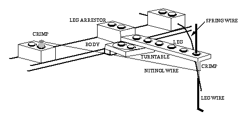
 The leg is formed by a horizontal
component made from a 1x6 LEGO plate and a vertical conponent made from
0.036"-dia. music wire. A hole is drilled in one of the LEGO studs and a notch
is cut into the side of the plate. The music wire is bent so that there's a
short horizontal component that the plate rests upon. The music wire is glued
into place for stability. The key modification is the use of a "spring wire",
made from 0.025" music wire, that is separate from the actual leg. The spring
wire is constantly pushing against the aluminum crimp on the leg wire,
providing an electrical contact. The nitinol wire can be activated via
connections to the crimp on the body and to the body end of the spring wire.
When the nitinol is activated, the leg pivots on the turntable and pulls back
on the spring wire. Once current is removed from the nitinol wire, the leg is
returned back to its original position by the spring wire. The spring wire is
physically prevented from pulling the leg all of the way back by the leg
arrestor LEGO stud. The crimps are made as mentioned in the note for 15
September; the leg crimp has a 3/32" component that's longer than the 1/8"
component. The 3/32" portion is crimped to hold the nitinol in place. During
construction, if the nitinol has some slack, it can be pulled up by twisting
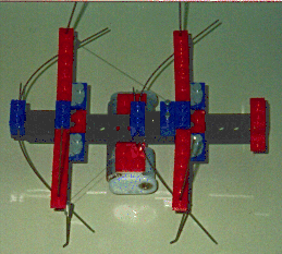
the leg crimp prior to the actual crimping. Please note that the body is also
made from LEGO bricks - I'm just too lazy to do all that drawing at this time!
:-)
I find the use of solar cells to be interesting as one could deal with more behavioral mechanisms with such a robot. What should the robot do when a room is dark? If there is a reliable period of light followed by dark, what would be the best way to organize one's "day"? Could a robot detect the place where the light is the most intense and refer to it as "home" for purposes of "sleep" (to recharge it's system)? What information could a small robot gather about its environment, and how could it be communicated to others?
A related design item would be to develop nitinol powered "tongs" so that the robots could interact with the environment instead of just maneuvering through it.
I've mentioned the Basic STAMP earlier - it's small size and ready accessibility would make for a good on-board controller for the masses - all that's needed is the interface for the nitinol drivers. The STAMP is made from a PIC microcontroller; a design based on a high-end member of the PIC family would make for a better controller for those who like assembler.
Developing controllers based on low power designs would help to expand the amount of time that the robot could operate on a single battery charge. Some of the 3V versions of the 6811 would do nicely here, and versions of the PIC can operate at 2.5V and go into sleep mode. Limiting the peak current demands would also be of interest. This would require research into seeing if a single 180 mA current source could be multiplexed to the legs requiring movement: can a pulse train work in place of a continuous current supply?
